1. What is it all about
1.1 What the IQarium is
IQarium is the simple Android application, which allows you to control Home Automation or any Automation System based on Programmable Logic Controller (PLC). If you know what the PLC is, then you will probably know how to use it. IQarium is made by the PLC user (me), so I’ve implemented all functions which were important for me. But, I need to confess I’m probably addicted to Android development now, so I am quite ready to follow any suggestions from YOU. Other words, YOU have this incredible chance to influence the IQarium development path. The only things required are your comments to ideas or work we’ve already done.
1.1.1 Three principles of IQarium
Here are three principles of the IQarium, which I’ve defined long time ago:
a) IQarium is some kind of thin-client for PLC – IQarium is just presenting the user interface, it must not do any complicated maths or algorithms. Logic must be implemented within PLC itself. Why is it so? It’s easy the PLC is the mule running your home automation 24h/7. In opposite IQarium is the application which is started by you on demand, you are using it for a while and then you just exit it.
b) IQarium must have simple User Interface – when you use the application several times a day, like I do, there is nothing more annoying then complicated User Interfaces. I personally don’t like questions like: “are you sure..” or “do you really want to ..” or annoying sounds or complicated boring menus. Less number of screen touches = better User Experience.
c) IQarium must be free available and designed by the users not developers – end users are great, first of all they know nothing about technology restrictions, so everything is possible – in fact it is!
so, if you have your dreamed application for home automation in your head – write about it in the comments – if you idea is ground breaking I will implement it!
1.2 What the IQarium is NOT and never will be
– It will never be a “spy” application and – it will never use more android “privileges” then it is required – it will never be tested on animals :). I ‘m doing it for fun and fun only for my own Home. Believe or not, it is always great to do something important for someone else next to you absolutely free. Check it out, you’ll see. – it will always use XML file for User Interface rendering. Since the configuration is done only once, it is the waste of time to create “drag-and-drop” UI editor. XML file is self explanatory, so you can use any text editor to set-up it.
1.3 How IQarium looks like
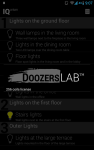
IQatium uses the simplest Interface ever made based on ListView in Android. I have 8 circuits controlled by PLC at my home (so far) so I do not have to scroll it very long to switch any of my lights. I believe I will have to add some more screens for room selection or so.
Here you have some screenshots – have fun
-

- Main and only screen
-
- About page
-

- Starting application…
1.4 How to get it
IQarium is available freely at Google Play. The Google Play is the only official source of updates and application itself. Any other websites, which are providing IQarium have no permission to do so.
Check it out here: https://play.google.com/store/apps/details?id=eu.kleniu.modbus.modbusMobGUI
2. How IQarium actually works?
IQarium is the simplest SCADA (Supervisory Control And Data Acquisition) ever made. IQarium is using the simplest protocol for communication with PLC which is Modbus TCP. Since the protocol is supported by all known PLC controllers I’ve implemented it in IQarium. Believe me it is really simple to understand – download and read http://www.modbus.org/ – after 15 minutes you will be a master of Modbus TCP protocol. IQarium is using my own Java Modbus TCP library for communication with PLC. I did it in Java because my lovely wife Catherine doesn’t like smart-phones and she is using MacBook for daily work, so I prepared simple command interface where she is able to control lights at our Home. Simple and efficient solution. So, yes, we have working text based IQarium for “OS X” too.
2.1 Modbus TCP functions used in IQarium (maybe to be extended!)
So far, I’ve four functions implemented in communication library which allows me to switch on and off single light at my Home.
- The first function (0x01 Read Coils) is used to scan the status of the binary outputs in the PLC. Since the communication with the PLC is always initiated by IQarium – the Modbus Client to be specific – the scan of current state of binary outputs (a.k.a Coils) is done in cycles. The frequency of the scan is defined in configuration file of IQarium, so you can tune it.
- The second function (0x05 Write Single Coil) is used to toggle/set/switch on/switch off the state of the binary output. Since each of my binary outputs is controlling single electrical circuit, by setting the the output to 1 will switch selected lights on.
- The third one (0x03 Read Holding Registers) is used to read the value of Registers associated with: control dimmers, curtains, temperature etc
- The last one is (0x06 Write Single Register) to set the value for Holding Register
That’s it! With these four Modbus-TCP functions you can control everything using your PLC. If you need some additional functions please drop me en email I’ll consider to implement them too.
2.2 IQarium XML configuration file location and name
Changing the configuration file is Required! You can configure IQarium and make it running according to your needs by changing the configuration file. The default configuration file is automatically created during first application start up in /mb/ directory on your primary external storage. The default configuration file (you never guess it) is called default.xml. To make IQarium running in your network you have to edit /mb/default.xml file. Optionally you can also copy /mb/default.xml file to different location under different name, because it is possible to define your own configuration file location and name in IQarium settings dialog. But, remember you have to always change the XML configuration file.
2.2.1 How to change the location and name of the default XML configuration file
Changing the name and location of configuration file is optional! If you want to do it, you will have to do it only once. First, as it was mentioned before, you have to start IQarium for the first time. Just start and exit IQarium, that’s it. The default configuration file will be created (remember /mb/default.xml). Then copy it to your own location with your own name. Next, you can run IQarium one more time and choose Settings icon on top right corner of the screen, as it is shown on the Figure 1 below
 Figure 1. Menu-Settings item
Then, you have to touch Settings item to show Settings dialog. The Settings dialog is very simple, there are two edit boxes, see Figure 2 below. In the first edit box you can provide the new directory on your primary external storage in Android where you XML configuration file is stored. In the second edit box you have to enter the name of the XML configuration file which you want to use.

Figure 2. Settings dialog
When you enter your values you will have to press Save button. If you do so the program will check the availability of the configuration file you provided. If the provided configuration file will not be accessible by IQaium the little message (called Toast) will be shown on the bottom part of the screen. Otherwise, the configuration file will be loaded to the application internal buffer and your directory and file name will be saved on internal storage, so you will not have to provide custom location and custom file name next time you run the application.
2.2 IQarium XML configuration insides
Very Important! I believe that this chapter is the most important chapter of the User Guide. I’ll try to explain the syntax of configuration file as simple as I can. I know, based on your feedback, that some areas should be changed or improved. I can ensure you that I’ll do so. By now, this chapter explains how it works in version 2.00 of IQuarium. Since I’m the author of the concept behind I’ll change this particular chapter in case of any conceptual change in code.
2.2.1 The Idea
The configuration file is the XML file. If you are not familiar with the XML syntax, you will have to learn one thing – its trivial but very powerful. First things first, XML file is just the text file, so you can edit it using any text editor. The text file means that there is no any hidden bytes of data in particular format inside – just pure text. You can use Andorid TextEdit or Windows notepad, wordpad or my favourite OS independent VI editor to edit the configuration file. When you display the file you will notice that all text inside is ALWAYS surrounded by keywords: <any_text> and </any_text>. These keywords are called tags. The text inside tag, in our example any_text, is defined by the creator of the xml file (that’s me in this case). In XML file we always use two kind of tags: start tag e.g. <any_text> and end tag e.g. . The data between the tags is the actual data needed by IQarium. I know that it is quite lame explanation of XML file, but it’s enough to configure IQarium. If you want to learn more about XML read excellent doc at http://www.w3.org.
2.2.1 XML tags used by IQarium
All tags names in IQarium configuration file are self explanatory, at least for me. I’m the author so it is obvious. If something in the concept is not clear for you or you just think that it’s too complicated – make the comment I will be very happy to make things easy. So let’s start.
2.2.1.1 Tags used to mark configuration data
<config></config> – These tags are just saying that everything between them defines the configuration data for IQarium. These tags are required, so you cannot skip them. You can find the first one (start tag) just in the second line of the configuration file. The second one (end tag) is in the last line of configuration file.
2.2.1.2 Tags used to distinguish XML format version
<version></version> – These tags are not used now (IQarium v2.00). I’ll use it in the future to distinguish the version of XML file format. It’s nothing to do with the version of IQarium application itself or the version of the file changes. I just need some kind of mechanism that will help me to check if the user (you) is using the current version of XML file format. As I said, I’m not using it now. You can write it here anything you want if only it is a number.
2.2.1.3 Tags used to distinguish the IQarium run mode
<mode></mode> – These tags are not used now (IQarium v2.00). I’ll probably use it in the future. You probably know, that if you have no TCP/IP connection with your PLC you cannot change the lights state – other words you will never see bright, shiny picture of the bulb which I’m very proud of. In the same time you may want to show your collogues, girlfriends, Santa Claus (ok it’s enough) how it actually works. So, I will probably develop something which is called “Demo Mode”. When you change the application state into demo mode you will be able to pretend that you will switch on your lights and so on – not very useful but funny. It is not implemented now.
2.2.1.4 Tags used for TCP/IP communication
<controllerip></controllerip> – it is PLC IP address. Very important value. You can also use here the network name as you defined it in you local DNS or any other name service. So, you can put it just IP like:192.168.2.50 or name: myplc.mycastle.eu.
<controllerport></controllerport> – it is just the TCP port for Modbus communication. Since the default TCP port on most PLC is just 502 you should not change it. But if you are using NAT or if you change the TCP port for Modbus you should change it also here.
2.2.1.5 Tags used for reading coils status
Before we start I have to describe one very important thing about Modbus TCP protocol. First of all you have to know, that Modbus TCP communication is always initiated by the modbus master (in this case IQarium application itself) – the PLC acts as the slave – it will answer only when asked. As in the real life, you know wife (master) – husband (slave) relation, and the definition of the perfect mate :). Seriously, it has some implications. If we want to check the current status of the coils you have to (IQatium has to) ask the PLC again and again for active coils.
<refresh></refresh> – is the delay in milliseconds between queries for coil status. By default it has 500ms value, so if anyone will change the output coil manually, for example by pressing wall switch – IQarium will display new status of the output coil after maximum 0.5s. The minimum period is 250ms – it’s hard-coded in IQarium because I do not want to flood your PLC with absurdly frequent queries. It is not good for PLC, Android with IQarium and probably your network switch. But it has also side effect – it is not the real time application. So it is absolutely not permitted to control nuclear plants, satellite’s trajectories etc. using IQarium 🙂
2.2.1.6 Tags used for screens definition
So far IQarium has single screen representing the lights in you home – very simple very efficient. But, I have an dream of having multiply screens in the near future, which can be associated for example with: temperature sensors, security cameras, weather forecasts, heating control – the sky is the limit. It will be also fully customizable by the end user using XML configuration file, so your imagination is the limit.
So far (v 2.00) we have one screen which representing lights.
<screen></screen> – everything inside represents or defines what information and how information is displayed on the screen.
<name></name> – is just the name of the screen. It is not used now since we have only one screen available in IQatium, so you can write anything here.
2.2.1.7 Tags used for items definition
The screen is build from items. Items have particular type, title and description. Items of some type can also have the icon representing the state of item and the address of the modbus coil or holding register. Please, check this chapter frequently, because you probably will be able to add new type of items soon.
<type></type> – in v 2.00 we have two kind of items type:
- group – which represents a single row in listview. The item of group type is not associated with anything in PLC (for example coils). Touching the item of group type do nothing at all. I’m using it for some kind of separator.
- row – items of this type represents a single row in the listview which can be used to control single coil (binary output in your PLC). Touching the item of row type will toggle/set the state of the coil.
- rowreg – items of this type represents a single row in the listview which can be used to control single holding register. Sliding the item to the right position will set the value of Holding register
<tittle></tittle> – is just the title of the item. Valid for item type: group, row and rowreg
<description></description> – is the description of the item. Valid for item type: group, row and rowreg
<iconon></iconon> – this tag is valid only for item type: row. It represents the name of the icon displayed when the coil is on. Possible values are:
- ic_bulb_on – default icon
<iconoff></iconfoff> – this tag is valid only for item type: row. It represents the name of the icon displayed when the coil is off. Possible values are:
- ic_bulb_off – default icon
<icons></icons> – this tag is valid only for item type: rowreg. It represents the name of the icon set displayed when the Holding Register has particular value. Possible values are:
- ic_stick – default icon
- ic_bars
- ic_bar
<coil></coil> – this tag is valid only for item type: row. It represents the address of the coil which must be changed when you press listview item on the screen. For example if you want to switch on Y4 binary output in the Fatek PLC which is associated by the vendor with modbus coil number 4 you have to put the same address (4) in this tag. Another example: if you want to switch on first binary output in the Beckhoff PLC you have to put address 32768 here.
<reg></reg> – this tag is valid only for item type: rowreg. It represents the address of the Holding Register in your PLC. In my PLC (FATEK) holding registers addresses starts from 180. I bet different PLCs have different addresses, because it depends on vendor implementation of MODBUS-TCP. Please verify it in your PLC documentation.
<coildisplay></coildisplay> – optional tag – this tag is valid only for item type: row. If you skip this tag in the configuration file then <coil></coil> value will be assigned to it. <coildisplay></coildisplay> represents the address of the coil which is read periodically to display coil status on the screen. If app reads coil status “1” then you will see <iconon></iconon> in the listview item.
<regdisplay></regdisplay> – optional tag – this tag is valid only for item type: rowreg. If you skip this tag in the configuration file then <reg></reg> value will be assigned to it. <regdisplay></regisplay> represents the address of the Holding Register which is read periodically to display it’s value on the screen.
<access></access> – optional tag – this tag is valid only for item type: row and rowreg. It can hold following values:
– rw – which is the default value in case you skip this tag. It allows the listview item to response to your screen touches.
– ro – which makes listview item “unclickable” on the screen
<mode></mode> – optional tag – this tag is valid only for item type: row. It can hold following values:
– toggle, default value – it will toggle the state of the coil after pressing the item in listview
– switchonoff – it will set the coil to ON status, then it wait abount 2 second and then set the coil to OFF status
– switchon – it will just set the coil to ON, regardless the current state of the coil
– switchoff – it will set the coil to OFF
2.3 Troubleshooting
If something is wrong and you are not able to set it up. Please drop me an email with the type of PLC you are using, along with the link to the documentation which describes the modbus configuration in your PLC. It would be very helpful to include the XML config file you are using, so I can recreate the problem in my local environment.

czy istnieje mozliwosc pobrania aplikacjii z tej strony , czsem latwiej jest w ten sposob….
I’m sorry, it is not possible to download the application directly from this website – it is very important for me to keep track of it. I do really encourage all users to use Google Play for installation because it helps me to fix bugs and ensure the quality of production release. As it has been written in the User Guide (chapter 1.4) the only way to install it is using Google Play. Any other websites, which are providing IQarium have no permission to do so.
hmmm , mam urzadzenie ktore posiada android w wersjii 2.3 i probujac pobierac te oprogramowanie niestety pokazuje mi w sklepie googla ,ze nie jest zgodne i nie pozwala zainstalowac 😦
Na tablecie z wyzsza wersja juz dziala , zauwazylem ,ze niestety sofcik nie widzi faktycznego stanu wyjscia ( fatek PLC) tzn jak zalacze z tableta i nastepnie wylacze to stan sie zgadza lecz gdy odpale programik a swiatlo jest wlaczone to nie widzi tego faktu i informuje ze jest off.
jak to dziala to nie wiem ale konfiguracja jest banalnie prosta 🙂
W konfigu na poczatku jest wiadomo IP i port to jest jasne
start adres o co tu chodzi bo np sterujac wyjsciem Y105 obojetnie co wpisze to i tak dziala …
Hi there,
ad1) Android 4.0 is the minimal required version for IQarium. I’m using some >=4.0 specific functions so it will not run on 2.3 – sorry. If I send you apk directly it will not install, as I said minimal android is 4.0
ad2) it must be something wrong with XML config file – please drop me an email with your XML config file and I will figure out what’s wrong with it. For security reason you can delete IP address.
ad3) if you wait few days I’ll describe in Users Guide the “how to” for startaddress and other XML items – they are very important
ok I can wait few days – no problem 🙂
But works perfect !!!
I have been playing with the software and it is pretty slick. I have a question though. I am using a Modicon Quantum PLC and you can not write to a real world coil that is in the PLC program. You have to write an internal coil like a normally open at an unassigned address. Therefore, I would need to be able to have a separate address for the display light bulb and the button to turn it off or on. I am also using Wonderware in my house to talk to the PLCs from computers but would love to be able to do it from my phone. I looked at Tesla on google play and it is a good phone based HMI but they want $200 a license and that is too much for a home owner and hobbyist.
Thanks and welcome 🙂
Let me summarize my understanding of the issue you have. As far as I understand you would like to have separate coil address for reading coil status and separate coil address for writing coil state associated with single listview item displayed by IQarium’s main screen. Is it right? If so, I do really like the idea – it adds much more flexibility. If not, can you please provide the users guide of Modicon Quantum PLC modbus-tcp setup? I’d be very happy to read about it because it seems to be very unusual how it works in your PLC.
Now, using my free time, I’m working on implementation of registry read/write function in IQarium, so it will be possible to control dimmers, curtains etc. I’ve also some other ideas how to improve functionality of IQarium. I’m just thinking how to prioritize these tasks. What do you think?
Yes you are correct about the coils. Lets say I have 000001 to 000016 assigned to my prist 16 point output card. Since they are assigned to real world I/O, I can not write to them. In the logic, I might right to 000200 to drive a latch for 00001 to turn on a light. I can also write to this same 000200 from Wonderware so either my phone or my PC could turn on the light.
Being able to read and write to the 400000 series registers would be great. Then I could monitor temperatures I already have connected to my PLC. I could also change the system clock or change the preset times when my outside lights come on all from a phone.
THe PLC I am using is a Modicon Quantum 140CPU113-02. Modicon has a lot of literature online if you want to look anything up. Here is a link to info on the 984 Ladder Logic http://www.modiconplc.com/pdfs/984-ladder-logic.pdf
Thanks,
Dan
Good, I got it. I’ve had a look to the manual and you are right all physical outputs are mapped into certain addresses in RAM. I believe that there is a little chance that IQarium can work with your PLC without code change. To be sure please tell me:
a) is it possible to read the value of 000200 using any MODSBUS-TCP client ?
b) If so, how this value of 0002000 is related to real state of the physical output 000001 ?
c) are these addresses (000200) in hexadecimal or decimal format ?
I do really like the idea of having two separate addresses (one for reading the status and another for set the state), but I would like you to be able use IQarium right now. So it is the reason why I’m asking these questions.
Hello,
a) You should be able to read or write any address between:
Output Coils are assigned the block 000001-099999
Input Coils are assigned the block 100001-199999
Input Register are assigned the block 300001-399999
Output Register are assigned the block 400001-499999
These are the default Modbus ranges and will work inside Modbus TCP since modbus is just encapsilated inside Modbus TCP. I wouldn’t worry about the 3x registers because those are just mapped to raw analog input, you usually then have to scale it in the PLC and save it into 4x registers. The same is true with the 1x registers, they are mapped to real world digital input I/O and if they are in the program you can’t write to them anyway. so only worry about the 0x and 4x reading and writing.
b) in this example, I might have a normally open contact at 000200 which when momentarily comes on, latches in the 000001 output. Then I set up a toggle in the PLC code so if 000200 is pressed again I unlatch output 000001. This way it is not held on. The best way is to alway write your inputs to the PLC as mementary and do the latching in the PLC so the bit isn’t held on. So Write 000200 to a 1 and then pause 1 second and write it back to a zero.
c) everything in the Modicon PLC is in decimal.
I am using 24 VDC momentary push buttons all over my house for lighting control. There are six buttons on 1 decora style light switch feeding 6 PLC inputs. These are real world and assigned to 1x addresses. In the logic I have 0x contacts in parallel with these inputs to drive the same logic from my PC based HMI. If I could assign these parallel 0x contacts in IQarium, it would just work in parallel with the PC based HMI. Either could set the monentary 0x bits. That would be excellent!
yep, the problem is that the modbus address 000001 (associated with physical output) is not writeable. It is totally different as it is in my FATEK PLC. FATEK allows me to write “1” into coil address 000001 so the physical state of first binary output becomes “on” too. I’m just thinking how to workaround this problem … well I’m not the ladder diagram guru but I bet there must be a quite smart way to “clone” the coil # 000001 which will be writeable. So if you write “1” to this “clone” of 000001 then the 000001 itself will hold “1” too. In the similar way if you write “0” to the “clone” of 000001 then the 000001 itself will have “0” too. Then you will have to control the “clone” of the 000001 using the IQarium and that’s it. But, as I said I’m not the PLC magician so maybe I’m wrong.
I have the filling that you have great experience with PLCs, so maybe you can confirm that it can work. If not, I will change the IQarium to have the separate address for reading the coil status. It will take some time, but it is possible.
Yes, absolutely. I think I can do it. One thing will be challenging – timing. How long do I have to keep the the coil in state 1 in the momentary 0x bit before I set it to 0? What do you think? 0,2s?
I don’t really know of a way to clone into 000001. I don’t think I can even write a 4x word into 000001 to 000016 because they would be assigned to real world I/O.
I would think 0.2 seconds would be enough time but you could always delay for 0.5 seconds and make sure.
Thanks!
Dan, I have a working beta version for you. If you’re interested drop me an email.
Hi, That would be great, I’d love to try it out. Thanks!
Hi
Great app, but did you think about KNX? I don’t know a lot of about this, so do you know how connect knx with IQarium and it is at all possible?
I make home mockup and I want to put there electrical installation with plc controller but I would have app in Google Chrome too. If you want do this I can help you when I will have done more in mockup 🙂
Yes I did and I’ve abandon the KNX due to it’s price and flexibility. So far you cannot use IQarium with KNX because KNX doesn’t support Modbus-Tcp protocol. As far as I know there are no any Modbus-Tcp gateways for KNX available on the market. Since I’m the developer of IQarium technically speaking it could be possible to control KNX, but at least 3 conditions have to be met: I must have specification of communication protocol used by KNX for communication in LAN, I have to have test device, I have to have time to do it. Unfortunately none of them are met. Sorrrrry.
Hi, I am searching for log time for such application.
I have great fun using it. Is there possibility to change some icons ? Or is there possibility to put image of my flat and see status of all devices ?
Is there a chance to download source code ?
If you want some custom icons in there you will have to send it to me. I’ll include it to IQarium repository.
For now there is no such possibility to display any image for visualization. I’m planning to do so, but for now I’d like to include some H.264 HD DVR video capture. I hacked the protocol used in some CCTV HD DRVs so it is pure implementation now. Unfortunately time is the only thing I need to finish it.
Witam,
Zaczynam własną zabawę z androidem i plc. Czy istnieje możliwość aby podesłał Pan jakieś źródła gdzie można poczytać o odczycie /zapisie zmiennych z poziomu android. Przydatne było by również może jakiś kawałek kodu z wytłumaczeniem.
Z góry dziękuję za pomoc
Dawid
Jasen ze tak, super że sie tym intersujesz – napisz o do czego chcesz ten kod uzyc